Satellite tracking antenna • HAM radio • ISS • Visual observing • Tracking software • Iridium flares • Satellite tracking system
Satellite
tracking
(BB_TRACKER
V4.6
21_March_2013)
LOW
COST
DRIVER
&
HARDWARE
FOR
THE ORBITRON
PROGRAM COMMAND
TWO
TV
ROTORS
IN A
PORTABLE
SATELLITE
TRACKING
SYSTEM IDEAL FOR FIELD DAY.
Aqui
em Portugês
INDEX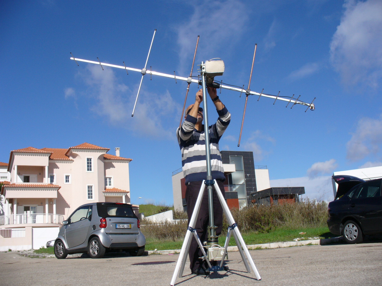
-
How
to install
the driver on the
Orbitron
and Dowload
the
Driver
-
KIT and
printed
circuit boards
-
Contact us
for
more
information
-
PHOTO GALLERY to understand the idea
Field day prototype test
http://db.tt/TOF7BLpN
(Thanks to GRC (Grupo Radioamadores Cascais)
INTRODUCTION
The
intention to enter
the world of
satellites and
space at low
cost, led us
to develop a
driver
for the program
Orbitron
able to command
two
rotors
of
moderate price,
thus, making
a system for
the
following
of
Satellites,
Moon, Sun etc.
The
complete system of
components
hardware
are
purchased from the
market
and
should
not exceed €
400.00.
With
the use
of reasonable
gain
antenna,
the system
optimizes the
contacts from
horizon to
horizon
and frees your hands.
The system
consists of
a
software
driver
that can
be downloaded
on the
link page
above.
This
Driver
extracts
every moment
the
Azimuth
and Elevation
of the satellite
selected in
Orbitron
and sends
them to
a
micro-controller
board
that will
control
the
rotor-controllers
through a
system
of
LEDs
indicators
PCBs
installed
over the
rotor-controllers.
We are
preparing a
manual
that explains
how to
assemble all the kit,
install
it
and
operate.
In the
following
lines we describe the
development of the
idea
for a Mule prototype being
that,
in the
end,
we will have
a system with
3 Printed Circuit
Boards
(PCBs)
with all the
electronics so,
it just will be
needed
to
assemble
the parts
according to the
instructions manual.
DIVER FOR THE ORBITRON
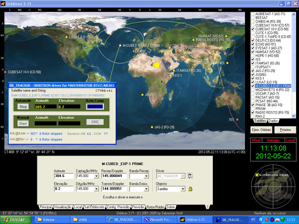
Aspect of the driver inside the ORBITRON
Before the compensation, this window previously notifies the operator that will carry out a compensation by coloring orange.
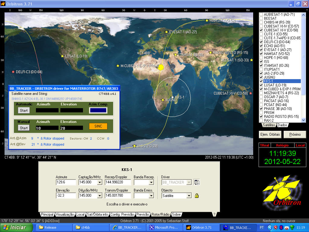
The
SINC
button is active
in
orange
color,
when
the driver is openned .
It is desirable,
before
the
passage
of
any
satellite,
to do
the compensation
and
synchronization
.
- Low cost system for satellite tracking.
- The system is a Kit that can be mounted by any ham with minimal knowledge.
- Driver works with Orbitron which is a satellite tracking program available for free downloading on the Net.
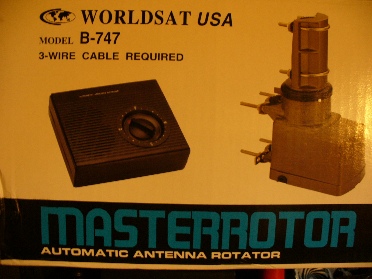
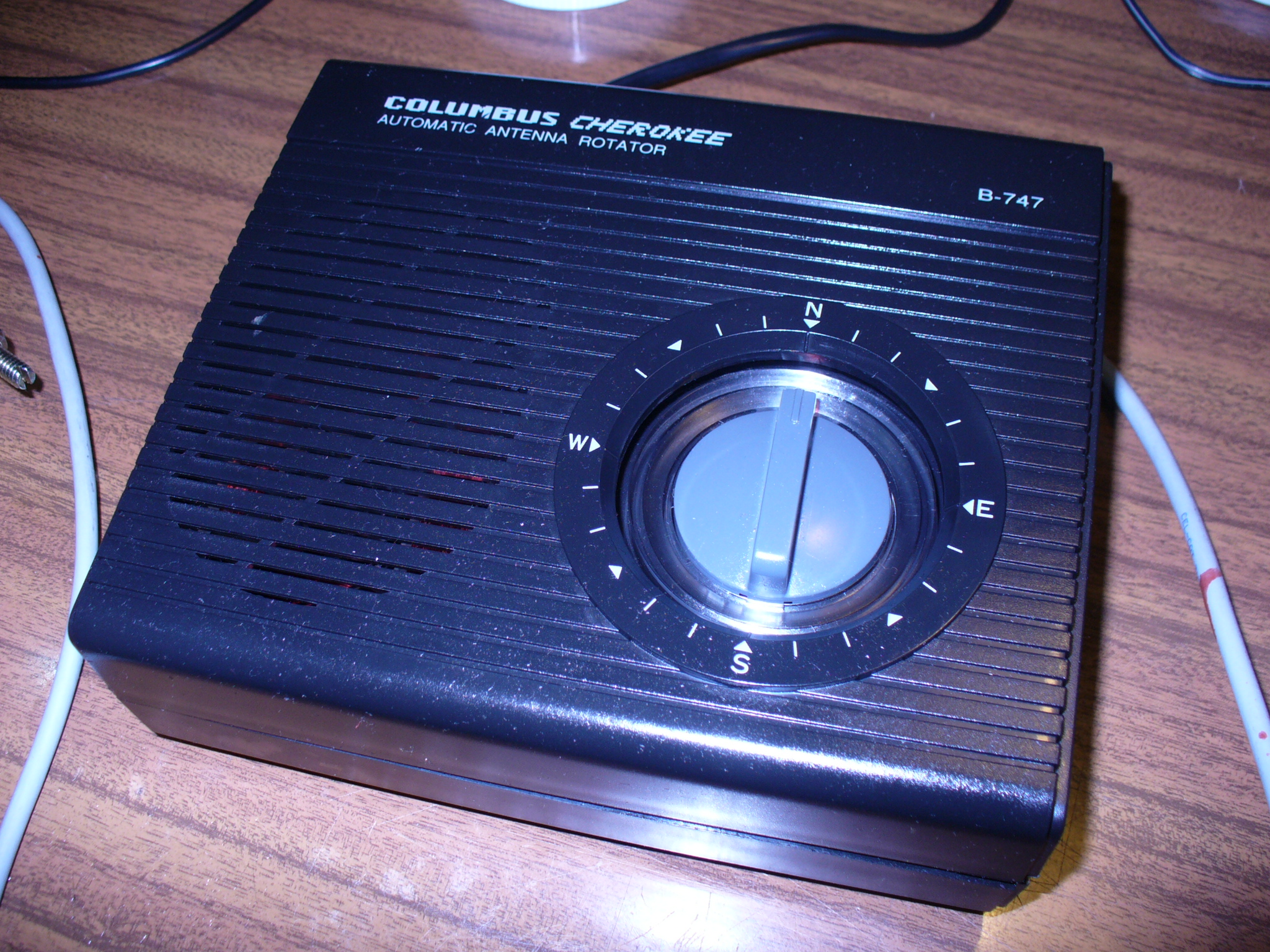
- Rotors used are type TV MASTERROTOR models B-747 or AR-303 which are well suited to the VHF and UHF antennas.
- The system has a precision of + - 3 ° that is more than sufficient for the opening angles of the antennas with 13 elements.
Costs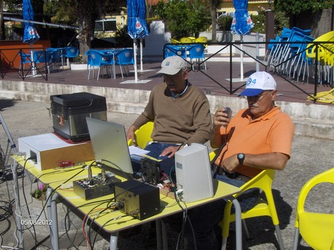
The total cost
of the System
wil be about
400.00
€.
- 2 rotors MASTERROTOR B747 AR303 to acquire in your local the market. (They are for € 50.00 each in Portugal.)
-
Our KIT with
3
assembled
PCBs,
and accessories
for
170,00 €
(Packaging & shipment included).
Note: you will bee
billed of VAT in your country customs
- Tripod or garden umbrella for about € 30.00. Purchase it on your local market. We got our from Leroy Merlin
- For the power supply use any 12V 2A . We used an old PC powe supply . Or get one for about ~30,00 €
- Time and patience to assemble the kit cost (€?).
Disadvantages
-
Rotors
are
low cost,
so, at
the end of
a 360
°
movement
some
+- 5º
comulative Azimuth error will happen
.
However, this
error does not
affect the
tracking of
satellites with
antennas
openings
of
+-
6º
at
-3dB
which
are
just the type of
antennas
we
use
for
VHF
and
UHF
for Amateur
Satellite
Comunications .
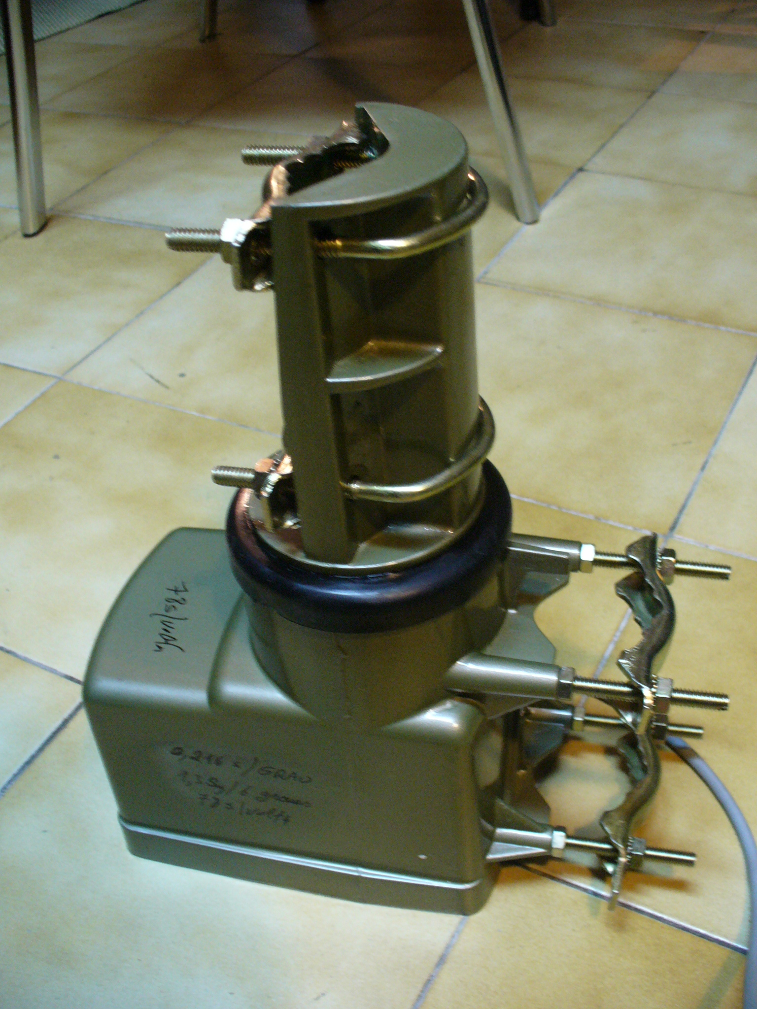
-
The antennas
should
be
installed
so that,
the center
of gravity
of the boom must stay
on the
elevation
rotor,
to avoid
slippage.
1 -
Use of an easy and friendly tracking
satellite program
ORBITRON
2
-
Low price
3 -
Suitable for
use in
tracking
LEO
satellites.
4 -
To modify
rotors,
it is only necessary
to
open the
azimuth
rotor
and saw
the
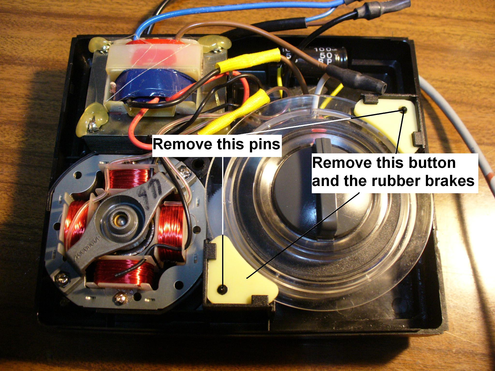
two
locking pins.
5
-
The system can
be synchronized
and
do not winds cables around the mast.It makes an automatic "Unrolling".
6
-
The placement
of the
Led
PCBs
is simple:
just remove
the buttons
and the contacts
of the controllers
and place there the PCBs.
7
-
The
system
allows anyone
with minimal
investment
and ability
to enter the
LEO
satellite
communications
8
- The system can
be also
be
remotly
controlled
by
entering
the
remote
PC
over the Internet..
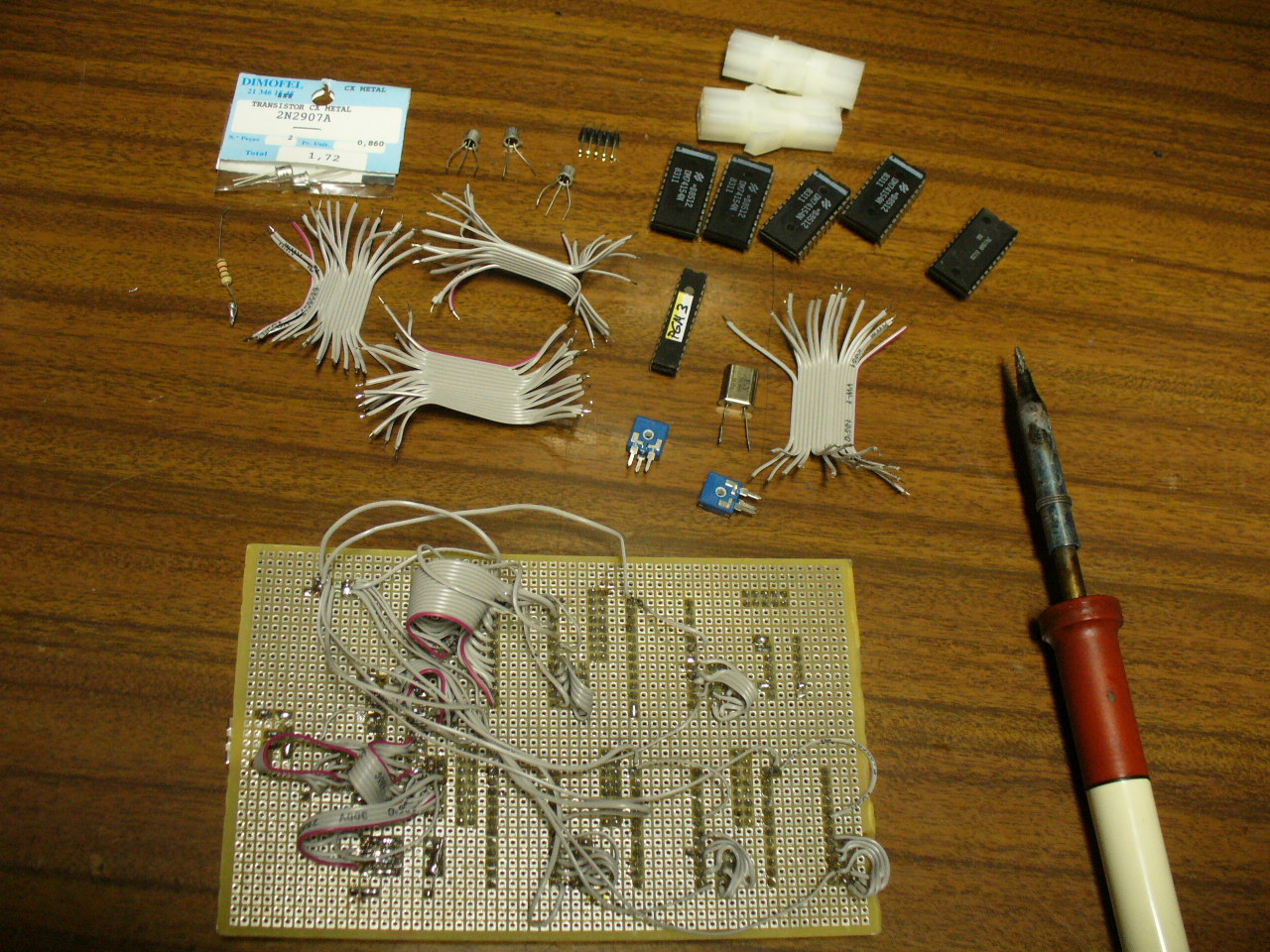
MULE PROTOTYPE
Hardware and software
needed for
the
portable system.
-
2
ROTORS
with
Controllers(type
MASTERROTOR
B-747
or AR-303),
1TRIPOD
(Quadripod),
1 TUBE
with 1.5m
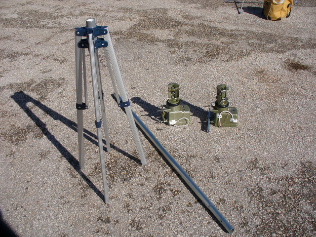
-
3
Printed
Circuit
Boards:
2
PCB/s
with position
LEDs
for
the Azimuths and elevations to mount
in
the controllers.
1
PCB Mother Board equipped with
a
microcontroller
to
place inside
the
chassis, or
box where
will
be
all
the assembly.
We have built
our prototype
on a
wooden board.
-
One
tripod
or an umbrella garden base
-
An
old
PC
power supply
can be used
where
we
take the
12
volt
~
2
A
minimum.
-
5
Flat Cables
with
16-conductor
with
2 x
ICD16
female
connectors
to connect the
microcontroller
PCB and
the
Led
position
PCBs.
-
2
x
10
meters
of cable
UTP
CAT5
4 pairs
to
send
the
control voltages
to
the rotors.
With
2 Power connectors and one DB15 male connector.
( You can avoid the multipin connectors, connecting the cable directly to the Rotors terminals 1,2,3).
- 1
Driver
with
free
Download
here
to be installed in
the
PC
following the instructions.
The program
BB_TRACKER
is
a
Driver
that runs under
Windows
and
is
inserted
in
the
Orbitron
configuration.
The
driver
receives data from
Orbitron
and sends
them to
the
PCB
equipped with
a
microcontroller
that
commands
the controllers
of the rotors
for
the azimuths
and
elevations.
The rotors and
the
controllers
have
synchronous motors.
For
azimuths,
we
made
a
printed circuit board
with
60
position green
LEDs in
circumference
at 6
degrees
angles
(Sectors
of
6º)
which are sufficient
to maintain
tracking
of
satellite
antennas
with
lobes
of
+ - 3
degrees
@
-3
dB.
The
elevation
PCB
have
15
LEDs
corresponding to
15
sectors of 6º.
In
the
rotating disk
of
the
controllers
we
installed
a
photodiode
which
detects
the
LED
light
stopping
in the center
of the respective
sector.
The
software
always calculates
the
shortest route
around
360 degrees
and walk
accordingly.
The program
also warns that
will carry out
a reset
of turns
for
compensation,
in order to avoid
winding
the cables
around the
support
of the antennas.
BLOCK DIAGRAM
![]()
1 - Turns on the LEDs of the azimuth and elevation where the rotors should move to.
2 - Connects the current supply of the drivers on both rotors through the relays RL1 and RL2
3 - Actuates the relay RL3 and RL4 to define the direction of the rotors movement : In azimuths if it is CW or CCW. In the elevation if it is 90 ° upwards (UP) or down to 0 ° (down).
When the photo diode reaches the lighting LED, it sends an information to the microcontroller to disable all the devices previously activated.
The relays RL5 and RL6 are intended to cut off the current from the rotors keeping the controllers working to synchronize the system.
The software
acquires
the
data
automatically
from
the
Orbitron
processing them
as follows:
- Extracts
the
data
through the protocol
DDE (Dynamic
Data
Exchage)
in a
Satscape
string
format.
- Inserts
data
in
the
reading windows
for viewing.
- Processes
the
data from
windows
comparing
the values with
the
ranges
of
sectors
and sends a
related
signal
to the angle-LED
where
the Micro
should send the
rotor,
the LED
lighting
sector
- The software
also compares
current data
with
the previous one to
know
which way
is
shorter
to
move the
rotor (CW
or CCW).
It
also calculates
the
number of
sectors
CW and
CCW to
where the rotor
will be
sent. It calculates the travelling of the azimuth rotor to
notice
to do
a
RESET
and
avoid cable turns around the mast.
-
Even after
turning off the
PC,
the data
of
the
Last
Position
of the antenna
is
stored.
-
In the case
of the
Last
Antenna Position
values
indicated by
the
program does not
match the
actual orientation
of the antenna,
it is because something
has been forced.
To fix
it,
just
press
the knob
SYNC
(when in orange)
that will
synchronize
the
system
- Button-Start / Stop to trigger the automatic tracking from Orbitron data.
- Start-button to activate the manual system with the windows where are inserted the intended azimuths and elevations.
- Button-SYNC to synchronize the actual orientation of the rotors with the controllers.
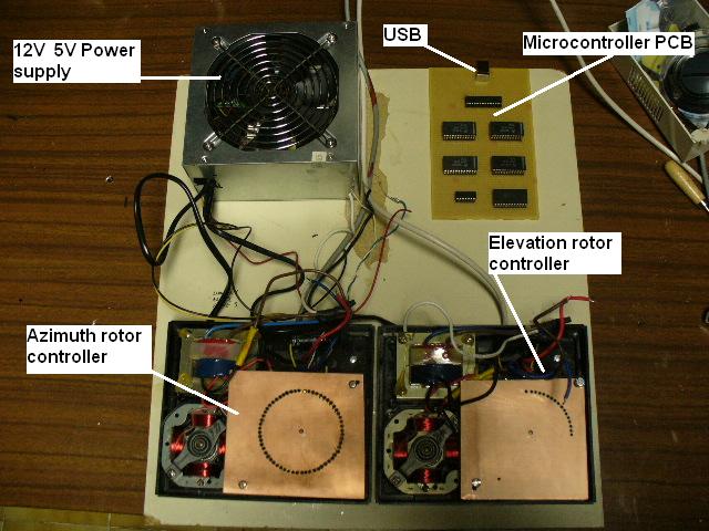
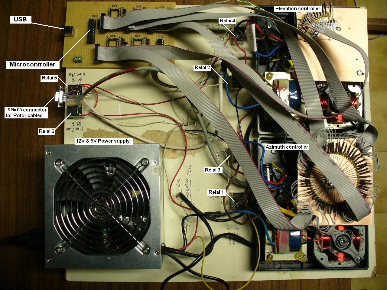
System
It uses a Software Driver running
with Orbitron, a microcontroller in a PCB accessed by the PC USB port,
which
controls the modified Controller Box.
The Software Driver receives data from Orbitron processes it and sends the commands to the microcontroller which, in turn, sends data control to the Rotor Controller.
HOW
IT WORKS
The concept is to
replace the
original controller button with an hardware which
simulates the manual operation.
This is done
replacing the
rotable
controller
dish
with a PCB with
leds which represents the
centre of
angle
sectors.
In the white
plastic rotable dish we put a photodiode which
detects the activated led and stops.
We divided one complete turn of 360º in 60 sectors of 6º each for the azimuths and 90º 15 sectors for elevations.
The reason for the sectors is to permit an antenna pause between +- 3º of satellite passage inside a 6º arc.
For example: the sector 5 will be between 24º and 30º and the antenna will be
pointed
in the midle
27º
during the passage.
As soon as the satélite azimuth is out of the sector, the software driver sends a command to the microcontroller to activate the next sector led and the (white plastic) dish of the controller runs 6º and stops.
SOFTWARE DRIVER FUNCTIONS FOR THE ORBITRON
The driver
catches the data from Orbitron with the DDE protocol in the Automatic mode or catches
data from the windows in the Manual mode.
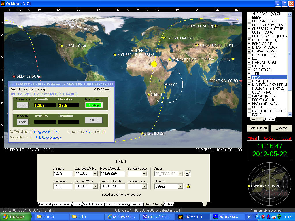
The movement of the azimuth rotor is free from any mechanical limitation so, it will be possible to turn more than 360º around without being interrupted in the middle of a satellite pass .
To prevent
that automatic resets occurs during the satellite passage, the RESET button
will become
In the
Manual operation, the Azimuth and Elevation are inserted in the windows to
command the antenna position.
The SINC button is to synchronize the physical antenna position with the system data. It can occur with heavy wind or data loss and the software position do not corresponds to the physical antenna position.
HOW WE DEVELOP THE PROTOTYPE
The only care is to balance the antenna placing it to the rotor in its center of gravity
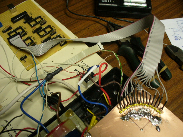
HOW TO MODIFY THE ROTOR CONTROLLERS
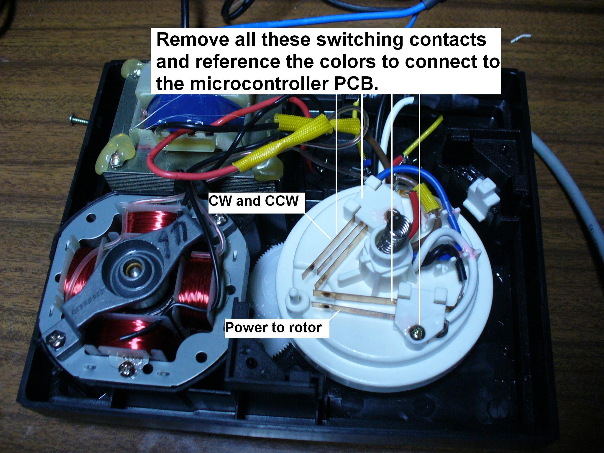
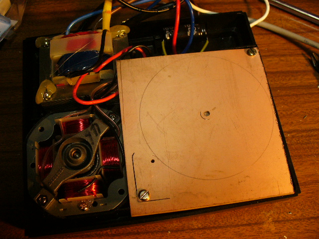
Contacts removed Aligning the PCB
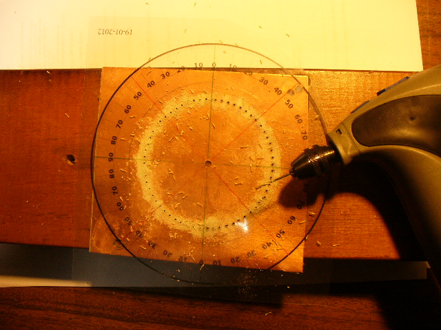
-
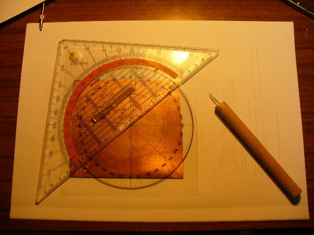
Marking holes for the leds Drilling of small holes
In the final stage, holes will be precisely placed by a PCB software design and professional PCB manufacturer.( SEE IT HERE )
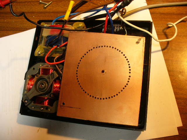
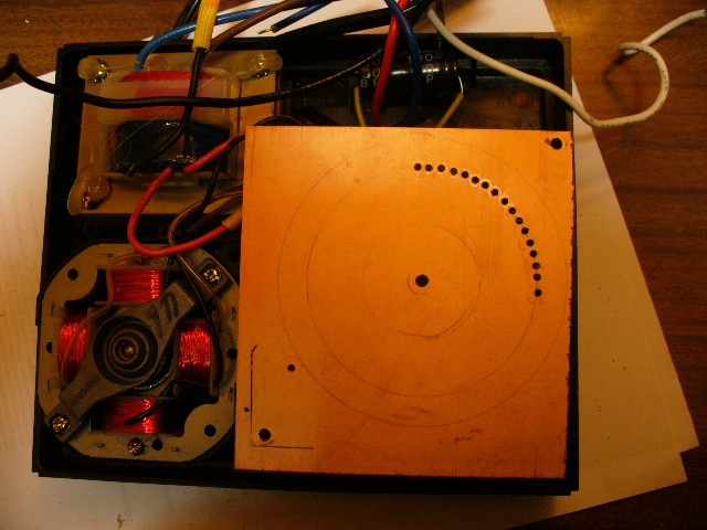
Layout
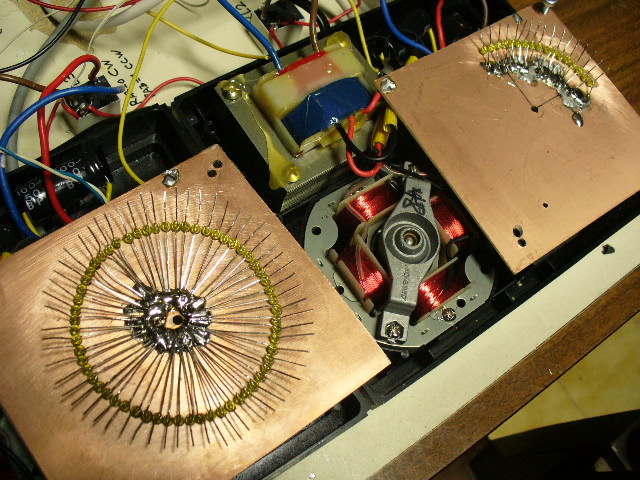
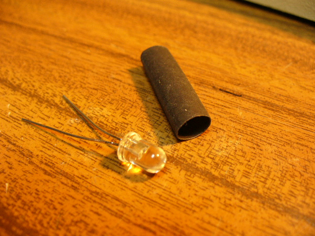
Placing the 60 LEDs on the disk of the azimuths AND 15 LEDs on the disk of the elevations. Phototransistor and shrink sleeve
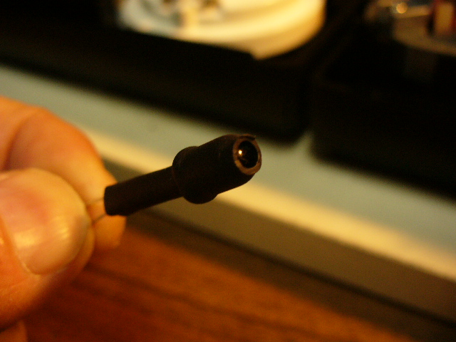
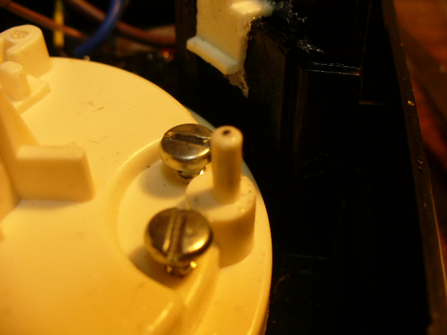
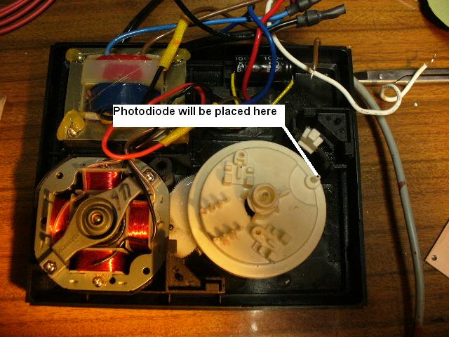
Sleeve placed on phototransistor Pin where to put the phototransistor
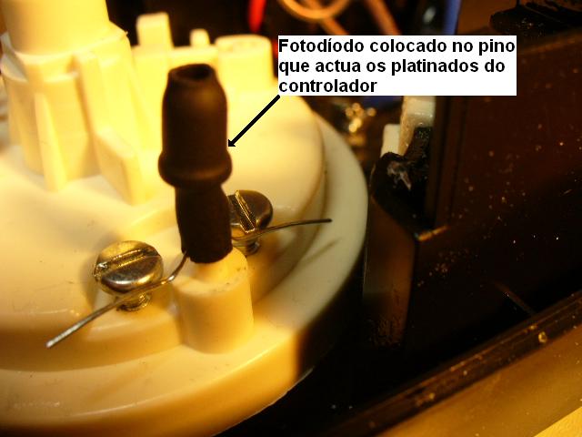
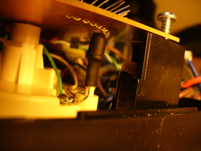
Phototransistor placed . Screws were removed because are not necessary. The sleeve stands the fototransistor. Photodiode will run down and around the leds.
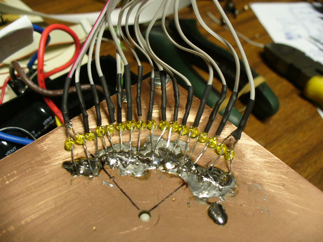
15 Elevation diodes placed. ( Note:Each diode representes the center of a sector of 6º ) Flat cable 16 connected to the Microcontroller PCB
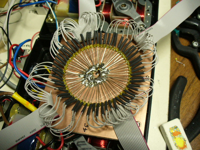
For Azimuth we have 60 sectors ( 60 leds) divided in four quadrants of 15 sectors. Four flat cable 16 wil connect diodes to the microcontroller PCB
Note : These two PCBs are a prototype design and will be replaced by the new comercial PCBs shown above.
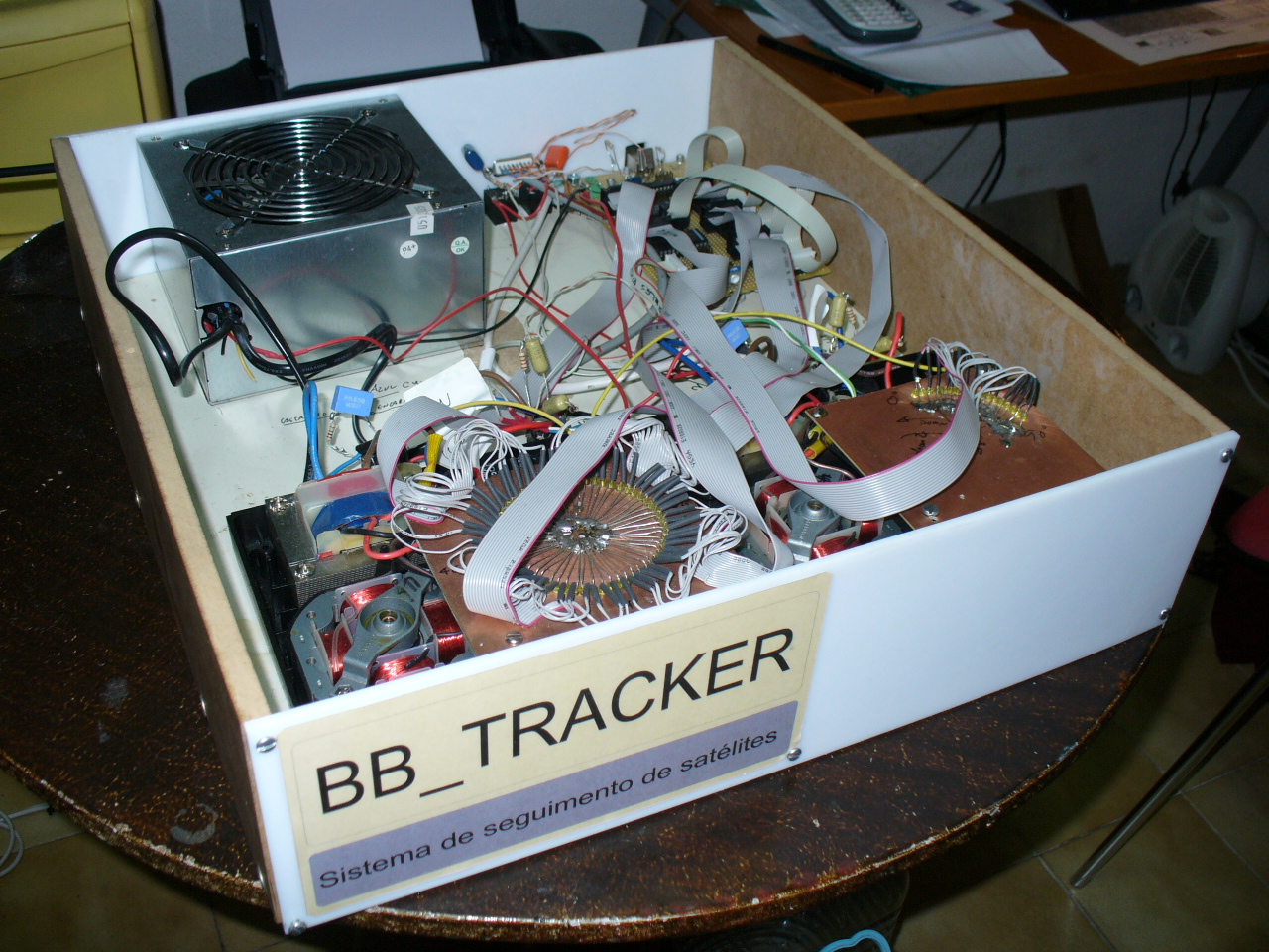
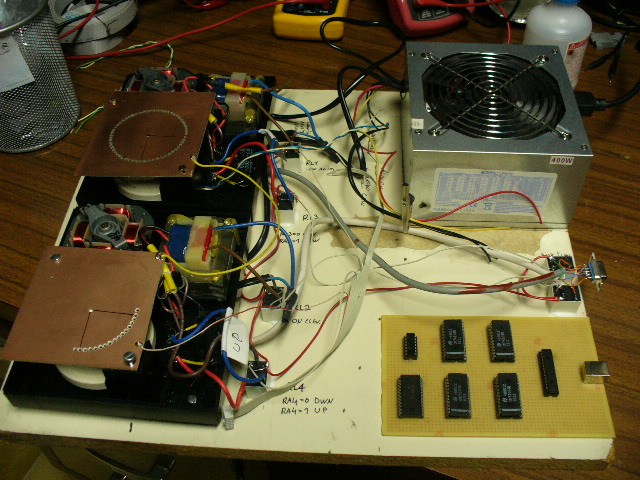
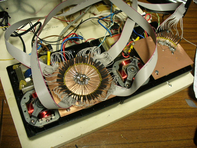
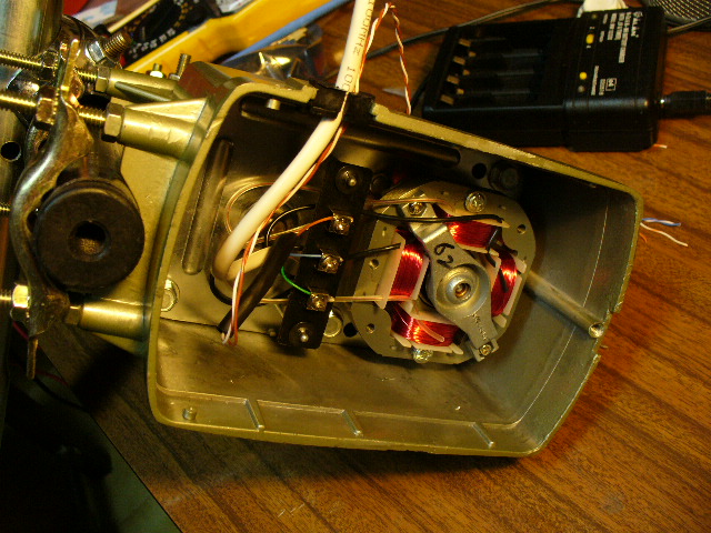
Assembled system to put in to a metalic box
All Relais, and wires, will be placed in a single PCB after this prototype
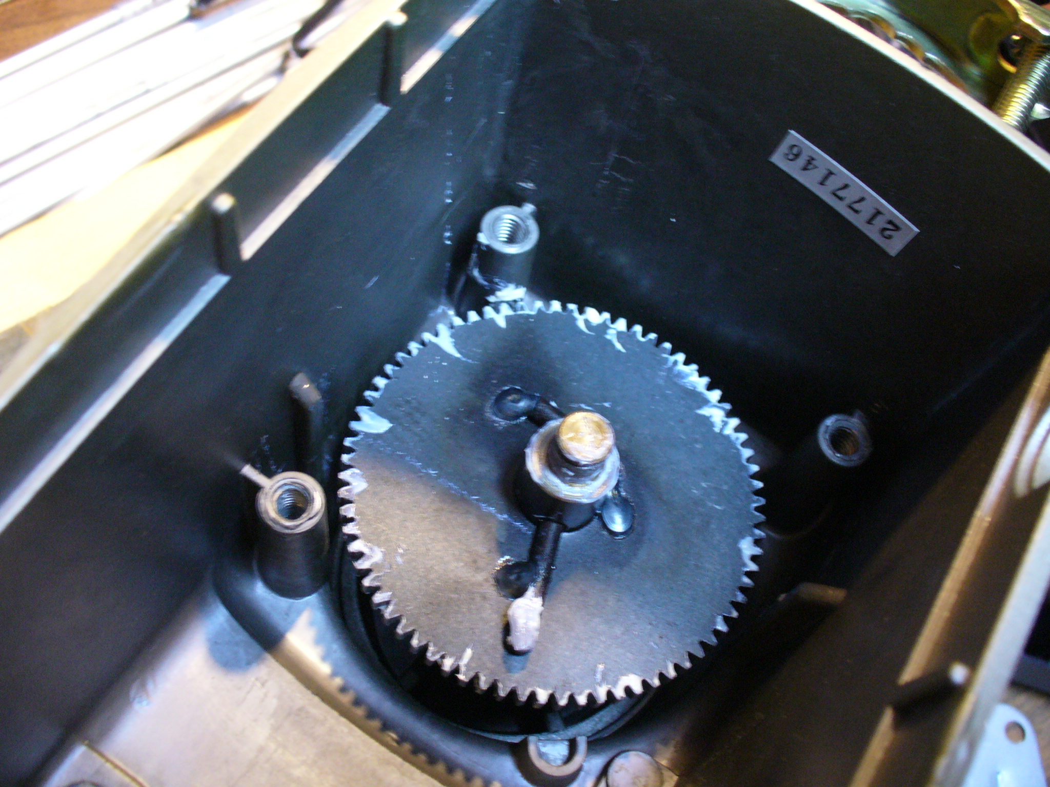
HOW TO MODIFY THE AZIMUTH ROTOR
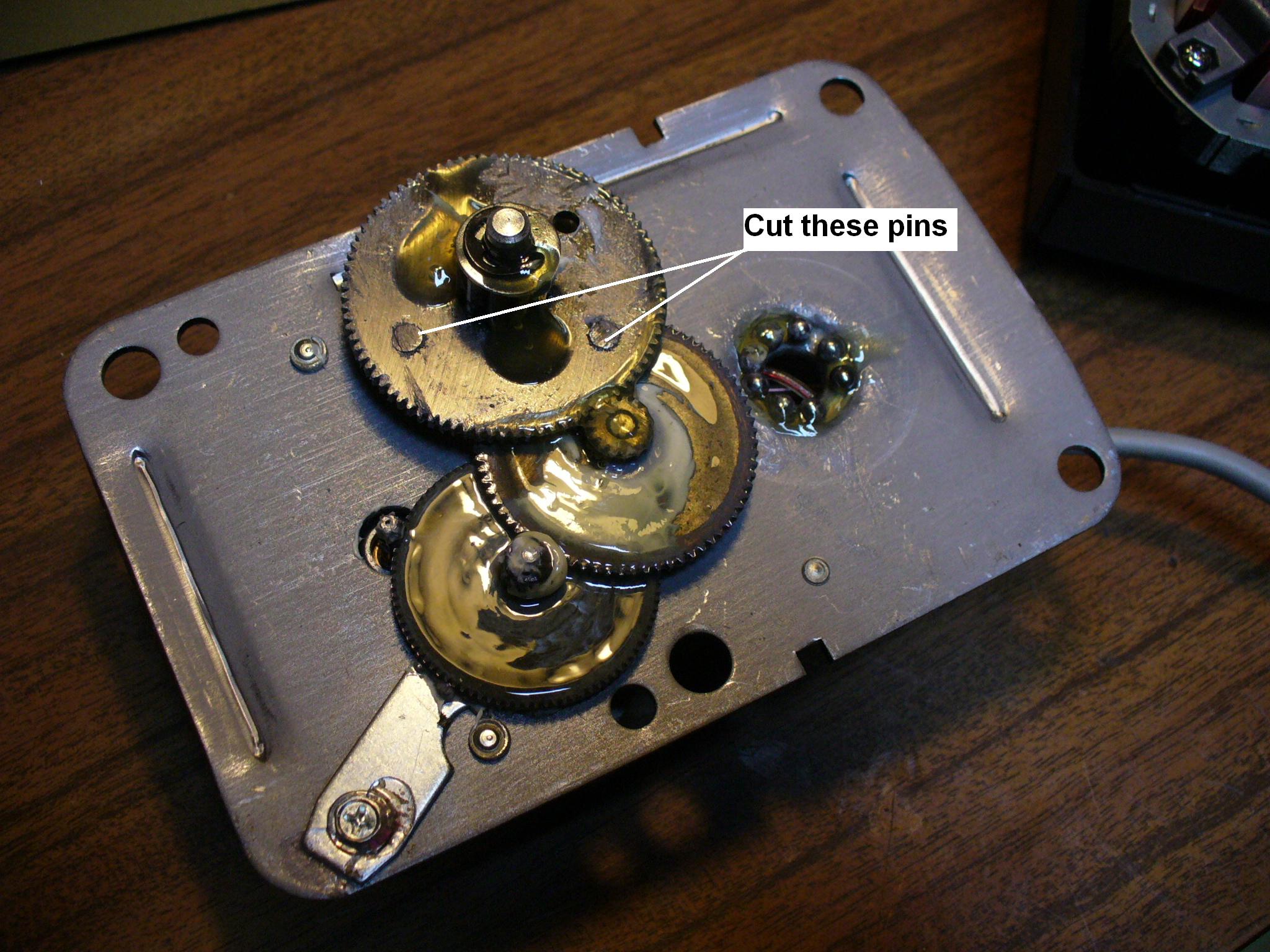
Remove the blocking pins in the gear
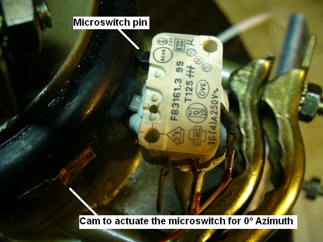
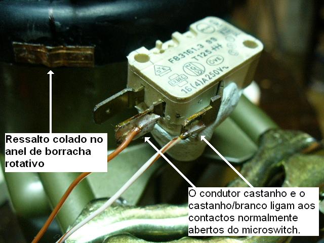
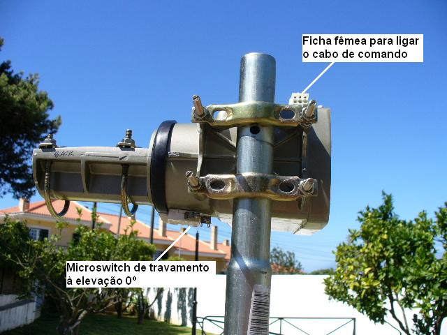
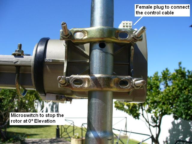
Exterior microswitch installed in the Azimuthe Rotor. The cam (ledge) switches on the stop at zero. The Brown and Brown/White wires belongs to the UTP CAT5 cable.
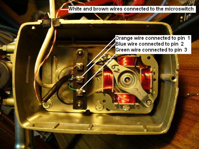
Wiring the UTP cable to the rotors. In both rotors, connections are the same.
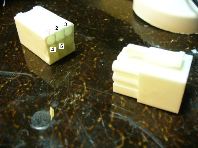
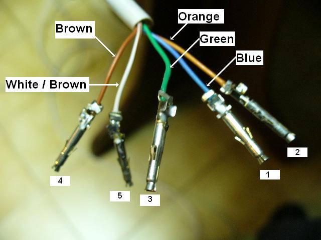
Connectors used and glued to the rotors to allow easy transportation. Soldering the female pins of the connestors
Note : These numbers are the numbers of the Pin connectors and the number of the DB15 Pin also. They are note the numbers of the Rotor terminal.
As
seen in the picture before;:
The Blue cable will connect to the pin 2
The Orange
to the pin 1
The Green to the pin 3 .
The Brown and White/brown wires will connect to the microswitch opened contacts in both rotors.
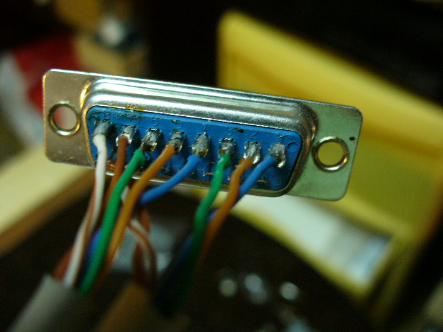
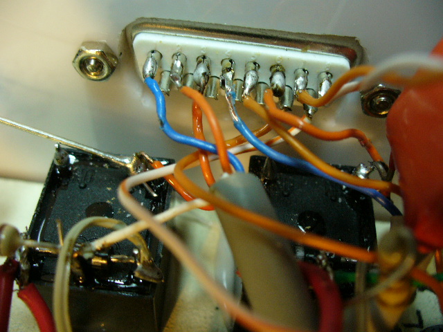
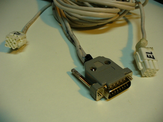
Soldering the two UTP cables (Azim.and Elev.) to the DB15 male connector Soldering the internal wires to the female of DB15 connector
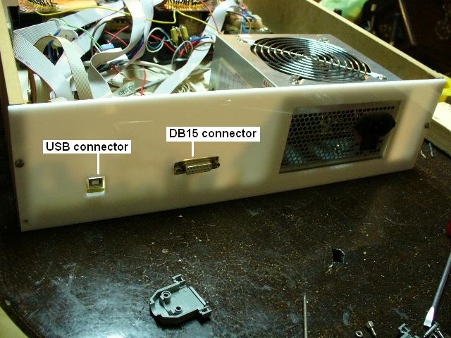
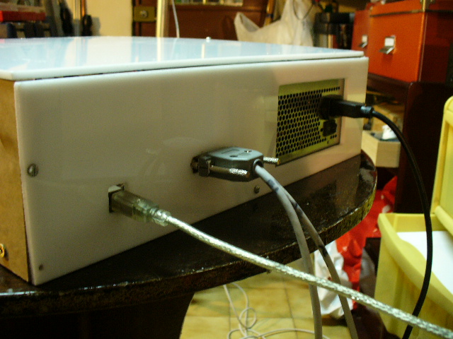
Back view of the prototype Box.
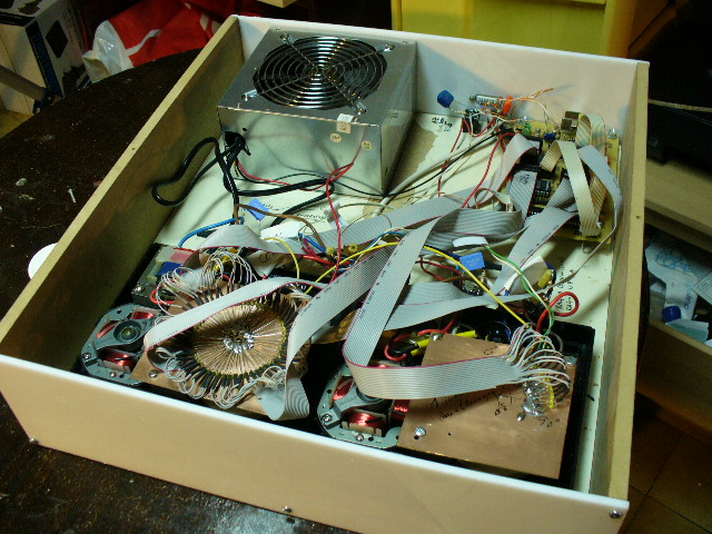
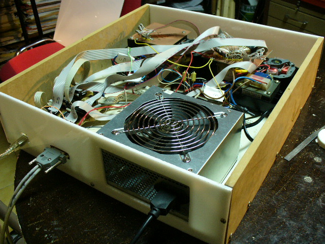
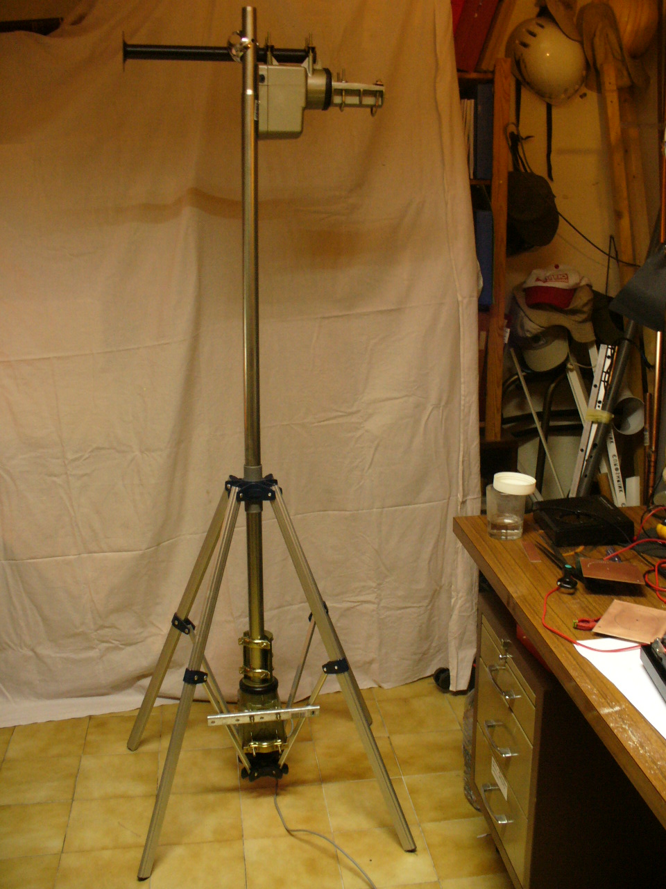
Top view
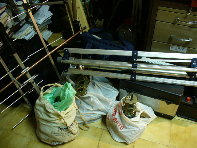
BB_TRACKER, Antennas, Rotors, Tripod, Mast and Radios ready for a Satellite Field Day...